Insights · 24 Sept 2026 · 6 min read
How the DQ200 Mechatronic Works: 8 Solenoids, 11 Sensors and the TCU Explained
In the Volkswagen, Audi, Seat and Škoda 7-speed dry-clutch DSG, the DQ200 (0AM / 0CW), one part runs the whole show: the mechatronic unit (J743). It is both the brain and the muscle of the gearbox — the electronic control unit (TCU) and the electro-hydraulic control unit share one housing. Knowing what each part does is the first step to replacing the right one.
In this guide we point out every solenoid valve, the pump and the pressure accumulator on a DQ200 mechatronic from our workshop, and explain the sensors and the control units the TCU talks to.
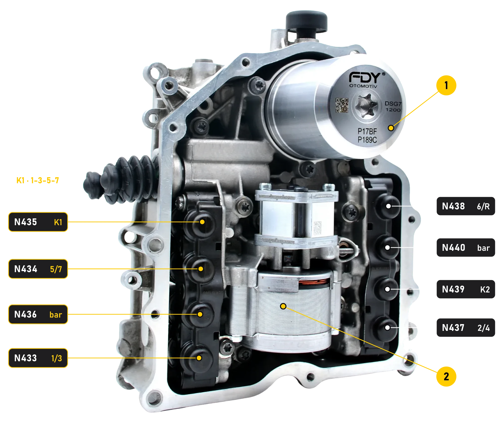
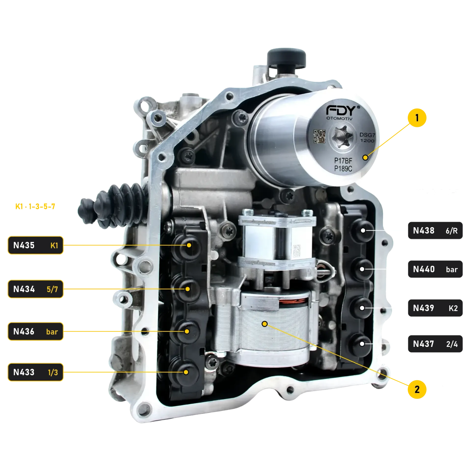
The tables below explain every code in the picture. In short: the four valves on the left run sub-gearbox 1 (gears 1-3-5-7 and clutch K1), the four valves on the right run sub-gearbox 2 (gears 2-4-6, reverse and clutch K2). Number 1 is the pressure accumulator, number 2 the V401 hydraulic pump and its motor.
First, the mechanics: two gearboxes in one housing
DSG stands for the German “Direktschaltgetriebe”, a direct-shift gearbox; the Q in DQ200 shows that it is designed for transversely (quer) mounted engines. Mechanically, the DQ200 is a manual gearbox with two dry clutches, two input shafts and three output shafts. The gears are changed not by the driver but by an electronically controlled hydraulic system — the mechatronic.
- Input shaft 1 runs inside the hollow input shaft 2. The gears for 1st, 3rd, 5th and 7th sit on input shaft 1; 2nd, 4th, 6th and reverse sit on input shaft 2.
- Reverse is produced by an intermediate gear on the second output shaft that drives the third output shaft. All three output shafts drive the differential.
- While you drive in one gear, the next gear is already engaged on the other shaft. During the shift one clutch opens as the other closes, and engine torque is reduced for a moment — the result is a fast, smooth change without an interruption in drive.
Hydraulics: its own oil, its own pump
The mechatronic has its own hydraulic oil circuit, completely separate from the gear oil. In this circuit the electric hydraulic pump (V401, number 2 in the picture) and the pressure accumulator (number 1) work together to keep the system pressure between 40 and 60 bar. The pump charges the accumulator, and the accumulator holds the pressure while the pump is off. The cylinders that move the shift forks and the clutch levers work with this pressure.
When the accumulator housing cracks at its attachment point, the system can no longer hold pressure, the pump runs more often and for longer, and the gearbox protects itself with pressure faults such as P17BF and P189C. The FDY reinforced accumulator in the picture was designed to eliminate this weak point for good.
8 solenoid valves: which one does what?
The electro-hydraulic unit has eight valves: four control the pistons that move the shift forks, two control the clutches and two set the system pressure of each sub-gearbox.
| Valve | Function | Sub-gearbox |
|---|---|---|
| N433 | Gear actuator valve for 1st and 3rd gear | 1 (1-3-5-7) |
| N434 | Gear actuator valve for 5th and 7th gear | 1 (1-3-5-7) |
| N435 | Pressure control valve for clutch K1 | 1 (1-3-5-7) |
| N436 | System pressure valve for sub-gearbox 1 | 1 (1-3-5-7) |
| N437 | Gear actuator valve for 2nd and 4th gear | 2 (2-4-6-R) |
| N438 | Gear actuator valve for 6th gear and reverse | 2 (2-4-6-R) |
| N439 | Pressure control valve for clutch K2 | 2 (2-4-6-R) |
| N440 | System pressure valve for sub-gearbox 2 | 2 (2-4-6-R) |
There is a hierarchy here: N436 sets the pressure that feeds N433, N434 and N435 in sub-gearbox 1, and N440 sets the pressure that feeds N437, N438 and N439 in sub-gearbox 2. That is why a fault in one of these pressure valves can take every gear on its side out of action at once — exactly the “only odd or only even gears” pattern drivers report. More in our article on DSG emergency mode.
Each valve can be measured individually. The FDY mechatronic test device measures the current drawn by every valve and compares it with the acceptance range, and the FDY Black Box tests and cleans solenoids on the bench.
11 sensors: what does the TCU measure?
The TCU makes its decisions based on the signals of the sensors below. All of them, except G182, sit on the mechatronic.
| Sensor | Measures |
|---|---|
| G182 | Gearbox input speed (outside the mechatronic) |
| G632 | Input shaft 1 speed |
| G612 | Input shaft 2 speed |
| G270 | Hydraulic system pressure |
| G510 | Gearbox oil temperature (on the control unit) |
| G487, G488, G489, G490 | Position of the four shift forks (one sensor each for the 1-3, 2-4, 5-7 and 6-R forks) |
| G617 | Travel of clutch K1 |
| G618 | Travel of clutch K2 |
The TCU does not rely on its own sensors alone. Over the CAN data bus it constantly exchanges data with the engine control unit (J623), the ABS control unit (J104), the instrument cluster (J285), the selector lever (E313), the steering column electronics (J527), the multifunction steering wheel (J453), the onboard supply control unit (J519) and the diagnostic interface (gateway, J533). Engine speed, for example, arrives over CAN; when that value is implausible, the gearbox stores P072600. For every code, see the DQ200 fault code list.
The electronic board (TCU)
The DQ200's control electronics originate from TEMIC; the unit was later produced under Continental and Vitesco Technologies. When the fault is on the electronic board, the hydraulic section is often still healthy, and the board alone can be replaced instead of the complete mechatronic — ask us about available boards. After a board replacement, a software update and the basic settings are required.
Notes from the workshop: common faults and checks
- Known symptoms: P R N D S flashing in the instrument cluster, a gearbox that will not shift, a blown 30 A fuse caused by a short circuit in the electronics, pressure loss and hydraulic oil leaks.
- Shift fork position sensor codes (P173A–P173D): the sensors and the magnets opposite them may be contaminated with metal chips. If they are, first check the gearbox for mechanical damage, then clean the sensor and see whether the code returns. How to read the chips is explained in our metal-chip check.
- The three speed sensors: check G182, G612 and G632 for metal chips every time the unit comes out. Contamination is a sign of internal wear; inspect the gearbox, then clean the sensor.
- “Gear cannot be selected” codes after fitting (P072A–P073C): these codes report that neutral, reverse or one of gears 1–7 cannot be selected, and they usually appear right after a mechatronic has been fitted. In most cases one or more gear actuator pins did not seat correctly in the shift fork; when fitting the mechatronic, make sure every pin engages its fork.
Frequently asked questions
01Which DQ200 solenoid controls which gear?+
N433 engages 1st and 3rd gear, N434 5th and 7th, N437 2nd and 4th, and N438 6th gear and reverse. N435 and N439 control clutches K1 and K2, while N436 and N440 set the system pressure of the two sub-gearboxes.
02What is the system pressure of the DQ200 mechatronic?+
The electric hydraulic pump (V401) and the pressure accumulator keep the system pressure between 40 and 60 bar.
03Does the mechatronic use the gear oil?+
No. The mechatronic has its own hydraulic oil circuit, completely separate from the gear oil, with its own oil filter.
04What happens if N436 or N440 fails?+
These two valves set the pressure of their sub-gearbox. If one fails, the TCU can switch that half off, and the car drives only in the odd (1-3-5-7) or only in the even (2-4-6-R) gears.
05Can the mechatronic board be replaced on its own?+
Yes, if the hydraulic section is healthy. First confirm on a test device that the pump, the pressure and the valves are fine; if the fault is on the electronic board, replace the board alone, then run the software update and the basic settings.
Mechatronic fault? Test it first
Before ordering a new mechatronic, test the unit on the bench: the FDY mechatronic test device measures the current of all eight valves, the pump run time, the pressure build-up and the leak tightness, simulates 1,000 shifts and prints a report. Send us your fault codes and our engineers will help 24/7 — contact us.
Keep reading